Consider a robot moving in an indoor scene, e.g. a factory or a museum, or a person moving with a hand-held device. We wish to build a 3D model of the scene and to track the robot trajectory in the scene using its sensors. This problem is known as the Self-localization and mapping (SLAM) problem.
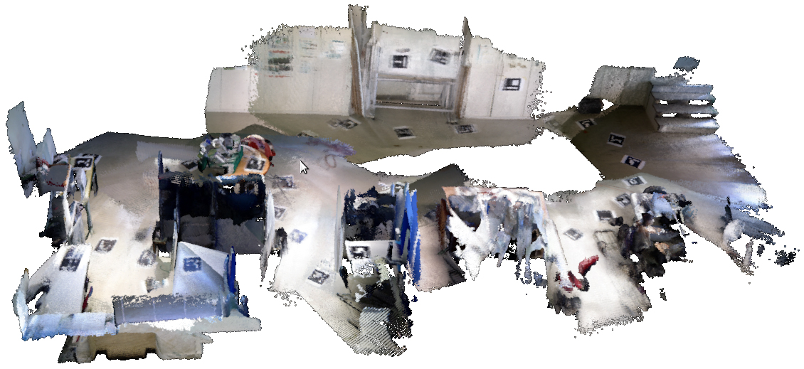
Figure 1 – 3D reconstruction of a scene
Sensors
The SLAM problem can be solved in many ways, depending on the type of sensors available in the robot. In this project, we assume that the robot is equipped with a Kinect sensor which includes a depth camera and a color camera. These cameras provide two images (depth and a color images) that have the same resolution and are aligned. This means that the Kinect provides the depth and color associated to each pixel (a cloud of 3D points and their colors).
Pose estimation and spatial integration
The Kinect sensor provides a local representation of the environment (cloud of 3D points) but this is not enough to reconstruct the scene from a single view since only local information is available. Therefore, we need to gather information from multiple views that has to be aligned and fused into a single 3D model of the scene. This can be done assuming that the robot (and the Kinect) moves along a trajectory and acquires data at different positions and orientations.
In each position, we need to compute the Kinect pose (position and orientation) with respect to the scene coordinates. After computing the Kinect pose, we need to fuse the 3D cloud of points obtained at the current position with the information obtained at previous acquisitions.
So, given a sequence of depth+rgb images the main tasks to accomplish are:
CODING PROTOCOL (Interfacing) for PROJECT 1 |
| your
code must have one main file named imagematching.m
as follows(you may have more files with other functions): |
| function [pcloud, transforms]=imagematching( image_names, depth_cam, rgb_cam,
Rdtrgb,Tdtrgb) ARGUMENTS: image_names - an array of structures with the names of the images. Each element of the array is a structure image_name(k).depth - a string with the path of the .mat file with depth data of image k. image_name(k).rgb - a string with the path of a jpeg/png file with rgb image k depth_cam - A structure with the intrinsic parameters of the depth camera depth_cam.K - a 3x3 matrix with the intrinsic parameters depth_cam.DistCoef - a 1x5 array with the lens distortion coeficients (you do not need to use these) rgb_cam - A structure with the intrinsic parameters of the rgb camera rgb_cam.K - a 3x3 matrix with the intrinsic parameters rgb_cam.DistCoef - a 1x5 array with the lens distortion coeficients Rdtrgb - a 3x3 rotation matrix Tdrgb - a 3x1 vector Rdtrgb and Tdrgb allow transforming 3D coordinates represented in the depth camera reference frame to the RGB camera frame RETURN VALUES: pcloud - [Xi Yi Zi Ri Gi Bi] - One N x 6 matrix with the 3D points and RGB data of each point, represented in the world reference frame (you choose the reference frame! For example, could be the depth camera coordinate system of the first image). transforms - an array of structures with the same size of image_name where each element contains the transformation between the depth camera reference frame and the world reference frame (as selected above) for image k. the fields are the following: transforms(k).R - The rotation matrix between depth camera and world for image k transforms(k).T - The translation vector between depth camera and world for image k DATASETS datasets http://printart.isr.ist.utl.pt/piv/stuff/NEWDATASET/ |
CODING PROTOCOL
(Interfacing) for PROJECT 2
|
| your
code must have one main file named peopletracking.m
as follows (you may have more files with other functions): |
| function tracked_objs=peopletracking( file_names, depth_cam, rgb_cam,
Rdtrgb,Tdtrgb) ARGUMENTS: file_names - an array of structures of size F (number of images) with the names of the files. Each element, say k, of the array is a structure file_name(k).depth - a string with the path of the .mat file with depth data of instant k. Depth image is obtained by loading this file that contains a variable depth_array with the depth image file_name(k).rgb - a string with the path of a jpeg/png file with rgb instant k depth_cam - A structure with the intrinsic parameters of the depth camera depth_cam.K - a 3x3 matrix with the intrinsic parameters depth_cam.DistCoef - a 1x5 array with the lens distortion coeficients (you do not need to use these) rgb_cam - A structure with the intrinsic parameters of the rgb camera rgb_cam.K - a 3x3 matrix with the intrinsic parameters rgb_cam.DistCoef - a 1x5 array with the lens distortion coeficients Rdtrgb - a 3x3 rotation matrix Tdrgb - a 3x1 vector Rdtrgb and Tdrgb allow transforming 3D coordinates represented in the depth camera reference frame to the RGB camera frame RETURN VALUES: tracked_objs - a cell array of size N (number of objects detected) where each element i has the following form: tracked_objs{i}= array of size L_i x 4 . L_i is the number of images where object i is visible. Each row of the array represents the position of object i at each time instant. Suppose object 4 appeared in frame 25 and you tracked it until frame 45. Then X Y Z t tracked_objs{4}=[X1, Y1, Z1 25; ...... ......... X20,Y20,Z20,45]; in total 21 rows XYZ is the position of the object (person!) relative to the ground. In other words assuming there is a ground plane, XY will represent the position of the person in the ground. Variable Z could be 0 (just represent the postion in the plane) or any value you choose to represent the object (e.g. the top coordinate of the object or the coordinte of its centroid...). The last column represents the image number where the object was located. DATASETS http://printart.isr.ist.utl.pt/piv/project |